Tri-bug
Project finished
Tri-bug is my first beambot since I started fidling with BEAM again. Obstacle avoidance is by direct mechanical means (push!), since I've found that feelers don't work that well with a bot this small unless you have back-up capability. It is a compact phototropic bot that was originally powered by the type-3 solarengine Tritium by Ben Hitchcock. However, it turned out Wilf Rigter was right about the problems with this circuit. As soon as the motor fires, the charging current increases and the solarengine turns off. Finally I settled on the T3SE V.5 by Wilf Rigter combined with the Dozer circuit by Darren Busson. I also had to perform a surgical reconstruction on a pager motor since the wire going to the brushes had broken inside the motor, very fiddly stuff. The T3SE/dozer combination works, but it behaves very eratically. Not sure what to do now, change to a Miller engine or keep trying with the T3SE? I have rebuilt the bot with a HC14 to do it's thinking and transistors driving the motors since I wasn't certain that the HC14 could drive the motors directly at such low voltages as this bot is supposed to operate at. The bot will have connections to easily change solarengine, that way I do not have to rip it up if it doesn't work well enough. I've also decided to give the bot no less than 3 10*24 calculator solar cells wired in parallell with the 22*24. I want this to bot to be able to function in really low light! So, the bot is semi-finished. Right now it is running with a Miller solarengine, but it's easy to change it in the future. Also, the 1381J should be substituted for one with a lower trigger point. Since the bot only weighs 14 grams, there is a lot of "wheel"-spin when it fires. That is not effective power management. One funny thing about this bot is that its obstacle avoidance is better than my solarbotic photopopper, even without feelers. It is very sensitive to shadows cast by objects in its path, and even if it doesn't manage to avoid the object, the bumper guides the bot away effectively. Goes to show the importance of good mechanics, I guess.
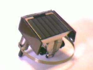
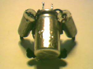
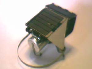
The finished bot. The "bumper" lets the bot interact with its surroundings more effectively. The solarengine (object with to large capacitor sticking out on the left) could use a little refinement, but it's only temporary...
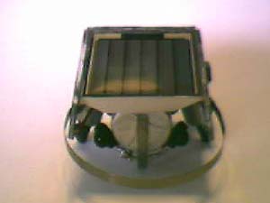
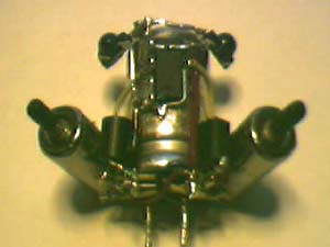
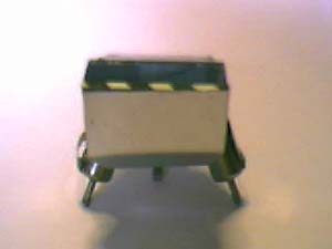
This is the chassis without solarengine and solarcells. In the middle picture you can see the motor driver transistors between the motors and the cap and the surface mount HC14 in the middle. The solarengine will go between the transistors.
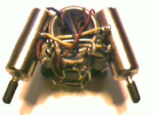
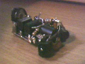
The bot with T3SE and Dozer circuit. First try, didn't work well.
This is the schematic for the T3SE/Dozer. Might be usefull if you want to freeform the circuit. Click for larger version.

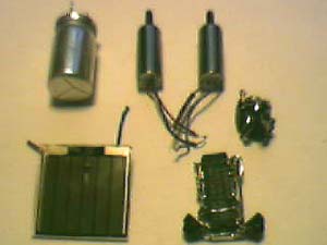
Here are the components for the first design. Clockwise from top left, 4700 uF cap, Namiki pager motors, freeformed T3SE, Dozer circuit and Panasonic 22*24 sunceram.
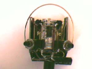
This is the free-formed tritium solarengine, built on a HC14. From left to right you can see the trim-pot, the NPN transistor, the two PNP transistors, and the two photodiodes. Took a bit of effort to get it this compact. Free-forming is fun! Too bad there are some problems with this circuit...
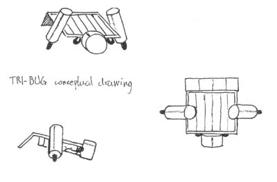
This is the original concept drawing I made when planning the bot.
 Specifications:
Capacitors: 4700 uF electrolytic
Solar cell: Panasonic 22*24 + 3 24*10 sumoncle
Motor: 2 * Namiki pager motors
Solarengine: 74HC14 "Dozer" circuit with transistor motor drivers, exchangeble solarengine (presently runing on miller solarengine with 1381J)
Sensors: Dual photodiodes, mechanical obstacle avoidance
Contruction time: appr. 20h, due to experimenting with different solarengines and motor breakdown