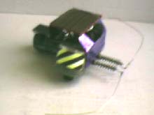
Welcome to the page devoted to my entry in Chiu's microvore contest. Granted, my bot isn't exactly in the micro format. Actually, I had planned to take the seriuos approach to this contest and really try to build a small photovore. However, since I am a college student, my budget isn't quite what is should be. Thus I decided to modify one of my earlier design just to have something to show. This was originally the third BEAM-bot I built, and it was designed to check if it was possible to make a photovore without the 1381 voltage detectors. The recent modifications concist primarily of making things look neater, since my original bot was pretty messy with loose cables everywhere:
Instead of using photodiodes, like the standard photopopper does, this bot uses photoresistors. This works pretty good, the bot can still move in almost as low light as my photopopper, not bad for a FLED solarengine bot. However, it's a good idea to wire a resister of apropriate value in series with the photo-resistor so there is some resistance even in bright light. Over the years this bot has developed some rather strange behaviour, nowadays it likes to move in a circle in full sunshine. Here's the schematics, made in MS paint, in all their splendor:
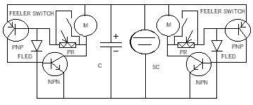
I think it's strange that no one else, at least that I have seen, has used this layout. It's a pretty intuitive and easy way of making a bot phototrophic. The theory of operation is, shortly, that on the side that gets the most light the photoresistor has a lower resistance and hence the SE works less efficiently than the side that gets less light. Because of this, the low-light side triggers first and drains the cap. The feeler-switches simply shorts the photoresitor on the opposite side (as opposed to what it looks like in the schematics) hence giving it zero resistance. That's it.
Copebot Specifications:
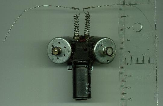
Motors: 2 walkman motors from old walkmans
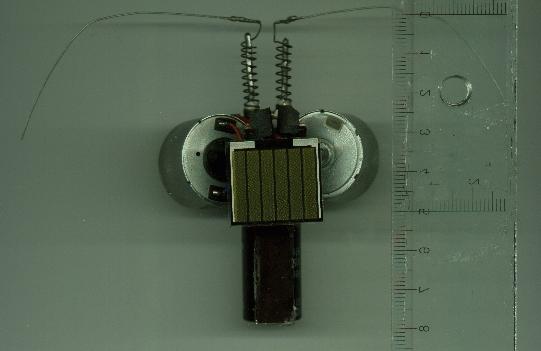
Solarcells: 1 Panasonic 22*33mm and 1 10*24mm calculator cell
Solar engine: Double Modified FLED solar engine with photoresistive biasresistors
Capacitor: 4700 microFarad from old modem
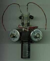
Feelers: Standard spring-feelers from guitarrstrings and clickpen-springs.
Estimated contruction time: Approx. 10 hours
Bottom view
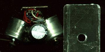
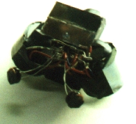
Backside view, showing the electronics beneath the solarcell
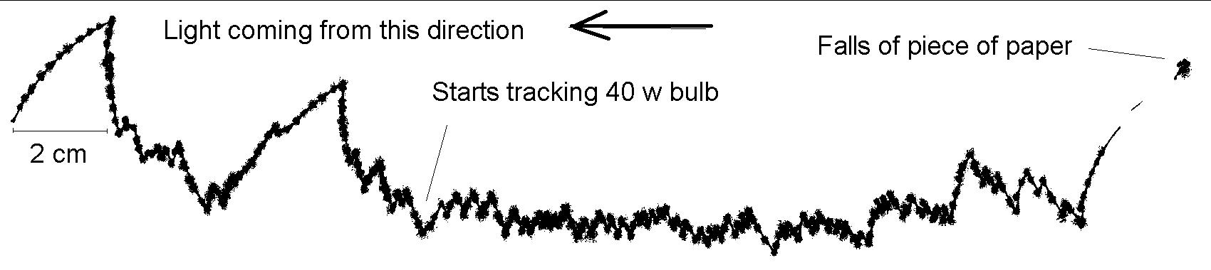
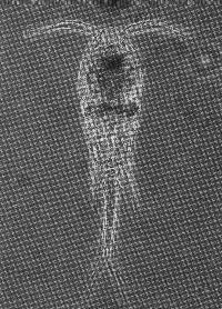
Behaviour. This picture was taken by placing the bot with a pen taped to it on a piece of white paper. The steps are
somewhat smaller than usual due to the increased drag from the pen. Every "blur" of the line is where the bot was still so the ink could
float out. Before the bot starts tracking, there was only ambient light in the room.